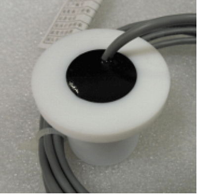

- #Driving piezo transducers generator
- #Driving piezo transducers driver
- #Driving piezo transducers series
A typical electrical drive power is 50-100 W and liquid cooling removes the heat. The water-loaded transducers do not need an exact frequency the resonance is wider ~5%, and efficiency, too.
#Driving piezo transducers driver
The power driver is typically a switching-type power amplifier, with a transformer. I did not make a high-power "cleaning" type devices but I repaired one. I think it does not matter if one drives the transducer by a rectangular or sinusoidal voltage. On the transmitting transducer, the waveform was rather pulse-like. At resonance (and quite sharp, like < 1%) the system response was clear and the waveform on the scope was sinusoidal.

The FET was powered by 12 VDC through a transformer on a ferrite core, and at resonance the voltage peaked over 100 V across the transducer.Īs I wrote, to check the function of my transmitter, I used another transducer connected to an oscilloscope. I used the 24 and40 kHz devices to transmit simple commands over a couple of meters, with a 555 as a generator, and some IRF power FET as the power amplifier. As their load is only air, they transmit some power by ultrasound with not much of efficiency. At resonance, they become resistive in their equivalent circuit. The piezo ultrasonic transducers are behaving like a ceramic capacitor. High-power transducers allow the peak-to-peak voltage over 100 V, but they can be damaged by overvoltage as well as by mechanical overload. Piezo transducers are capacitive, so you can build a transistor power amplifier with an output transformer like 500 to 5000 Ohms, and with added capacitors tune the output for resonance at 40 kHz, with transducer connected. To increase the output power ~4 times, connect a 7404 or a CMOS multiple gate after your 555, and connect the transducer between the input and output of the last gate.įor a higher output power, check transducer rating for a maximum voltage.
#Driving piezo transducers generator
You will see that the resonance at 40 kHz is quite narrow, so a fine generator tuning is needed. To see the best function,use another 40 kHz transducer connected to oscilloscope input (1 Ohm, 50 pf). The simplest way to drive a 40 kHz transducer is to connect it to the output (pin3) of a 555 connected as multivibrator at 40 kHz. There may be more as things come up, but a lot of my questions can be answered by hooking this thing up to an oscilloscope and seeing what happens.ĭriving piezo ultrasonic transducers can be easy or difficult, depending upon what acoustic power you need to generate. Is this thing polarized? I was under the impression that piezo-based things weren't exactly polarized (I probably am quite incorrect).

* The pins seem to imply that this thing is polarized in some way (one is longer than the other). Most of what I have designed for myself have been digital circuits that didn't need to take care of this a lot and I don't have a lot of money to be burning out parts because of back-emf spikes. Is there a more effective way than a 100 ohm resistor and a zener to take care of this? Its been a while since I have considered this kind of thing. * I understand that these things apparently create quite a bit of back-emf spike. If I use a square wave (lets say off of a microcontroller pin) as the frequency source (40Khz of course), will that work fine for driving this sort of thing after being amplified to the proper voltage? Or do I need to make a sine wave generator at that frequency? Others seem to show that inputting a square wave is just fine. Some places I have looked say that it needs to be driven by a sine wave. * I have a step up thing I found on dealextreme to get me the appropriate driving voltage.
#Driving piezo transducers series
So far, I understand ultrasonic transducers to behave like a series LRC circuit with a resonant frequency of whatever they are rated for (40Khz in my case). They are similar to the ones seen on the back of cars. The place I got them gives capacitance and such along with an optimal voltage of 20V. I have recently come into a couple 40Khz unlabled ultrasonic transducers. I am on a limited budget and want to make sure I get this right before I go blowing things up. I understand this sort of question is asked often, but most of them have at least started something and are mainly looking for ways to fix it.


 0 kommentar(er)
